19.03.2026 – “Linear Contact” Is an Oxymoron: Understanding Boundary Non-Linearity in FEA
Executive Summary
In structural engineering discussions, the phrase “linear contact in FEA” is frequently tossed around to describe simplified contact setups in finite element software. However, from a solid mechanics and mathematical standpoint, the term is a literal oxymoron. Contact interactions inherently involve changing boundary conditions—surfaces opening, closing, slipping, or sticking during loading. Because these state transitions constantly modify the active degrees of freedom and force the global stiffness matrix [K] to update, contact analysis is fundamentally non-linear. Understanding why true contact cannot be linear is crucial for setting up accurate simulation models and avoiding misleading numerical assumptions.
1. Why Contact Invalidate Pure Linearity
In classical linear elastic Finite Element Analysis, the governing system of equations rests on a single fundamental assumption:
For an analysis to remain strictly linear, the global stiffness matrix [K] must remain constant throughout the entire solution procedure. Doubling the applied load {F} must exactly double the displacements {u}.
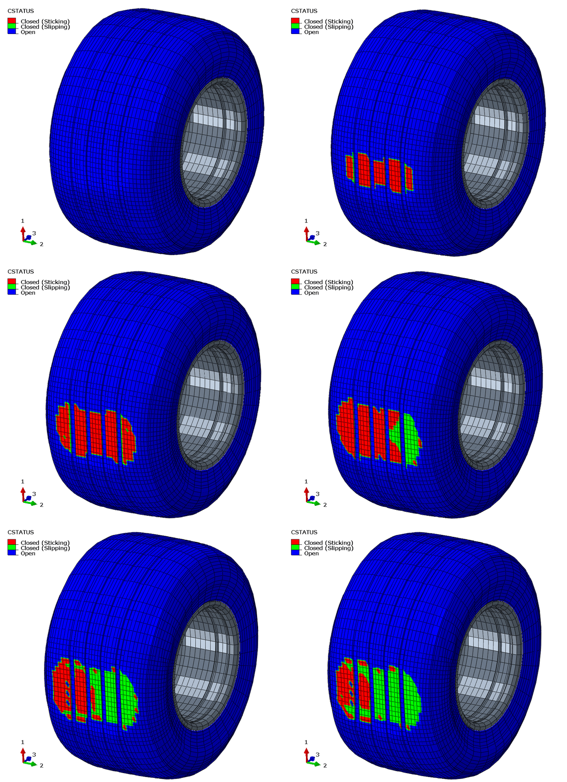
Contact interactions directly violate this assumption because contact is a form of boundary non-linearity. During a physical simulation, interface conditions continuously evolve:
- Opening and Closing: Surfaces in proximity may establish contact under load or separate as structural bending occurs.
- Slipping and Sticking: Tangential frictional interaction shifts between static friction (sticking) and dynamic sliding (slipping) depending on local normal pressure and shear stress thresholds.
Whenever a node makes or breaks contact, or transitions from sticking to slipping, the structural connectivity of the system changes. This forces the FE solver to recalculate and regenerate the stiffness matrix [K] dynamically—which is the exact defining characteristic of a non-linear analysis.
2. The Only Exception: When Contact Is Not Really Contact
Is there ever a case where a model with contact exhibits a constant stiffness matrix [K]? Mathematically, yes—but only under one strict condition:
The Tied Constraint Assumption: The only scenario where the global stiffness matrix [K] remains unchanged during a contact simulation is when the contact status remains completely static across all steps. However, if two surfaces are permanently locked together and prohibited from opening, separating, or slipping, the interface is no longer behaving as a contact interaction—it has effectively become a TIED (bonded) constraint.
Calling a TIED interface “linear contact” is a misnomer. A tie constraint simply enforces kinematic constraint equations (such as Lagrange multipliers or multi-point constraints) to lock degrees of freedom together. The moment you allow true contact behavior—where surfaces can react to normal forces without transmitting tension—linearity disappears.
3. Practical Implications for FEA Workflows
Engineers often seek “linear contact” algorithms to speed up computation or perform linear frequency/buckling steps. However, recognizing the non-linear essence of contact leads to better solver management:
- Iterative Solvers & Convergence: True contact problems require incremental-iterative Newton-Raphson solvers to establish equilibrium at each load step.
- Pre-Load & Linearization: For linear perturbation steps (such as natural frequency extraction or modal dynamics), contact conditions must first be established in a non-linear static step. The software then linearizes the contact state around that pre-loaded equilibrium position.
- Penalty vs. Lagrange Formulations: Choosing appropriate contact formulations (e.g., penalty stiffness vs. exact enforcement) impacts both solution speed and convergence stability when handling complex contact search algorithms.
4. Conclusion
While marketing material or simplified software interfaces might use “linear contact” as a shortcut for fast linear tie formulations, it is essential for structural engineers to remember the underlying physics: contact mechanics and linearity are mutually exclusive.
In Chapter 12 of my book, Computational Structural Engineering, I guide readers through the mathematical foundations of contact surfaces, surface-to-surface vs. node-to-surface formulations, and practical numerical methods to achieve robust convergence in non-linear contact problems.
