13.04.2026 – Simulating Wheel Bearing Preload and Compliance in High-Performance Race Cars
Executive Summary
In motorsport engineering, wheel bearings represent a critical yet frequently underestimated link in the load path between the tire contact patch and the chassis. While failure of a wheel bearing constitutes an immediate race-ending event, sub-optimal bearing performance subtlely compromises lap times by degrading suspension geometry stability and dissipating drivetrain power.
This technical article examines the mechanical delicate balance governing wheel bearing axial preload. We analyze the failure modes associated with excessive and insufficient preloads, explore how surrounding component compliance (hub, upright, and spindle flex) alters operating clearance, and outline an efficient Finite Element Analysis (FEA) methodology to model bearing stiffness without explicitly discretizing rolling elements.
1. Introduction: The Strategic Importance of Wheel Bearings in Motorsport
Wheel bearings in modern racing applications operate under extreme combinations of high cornering loads, dynamic braking forces, aerodynamic downforce, and elevated temperatures transferred from carbon brake systems. Despite their small footprint, wheel bearings govern two vital vehicle performance metrics:
- Mechanical Power Loss: Rolling resistance within the bearing directly parasitizes power delivered by the Power Unit (PU).
- Kinematic & Camber Stiffness: Flexure or play within the bearing raceways leads to uncontrolled wheel angular deflection (camber and toe degradation) under lateral loads, deteriorating tire grip.
2. Mechanics of Bearing Preload: The Operating Window
Bearing internal clearance and initial axial preload dictate the contact stress distribution across the rolling elements (balls or rollers) and raceways. Achieving the optimal working window for operating preload is challenging because the static assembly preload changes significantly under mechanical and thermal operational loads.

2.1 Excessive Preload Hazards
Setting an initial preload above the optimal threshold introduces severe structural and dynamic penalties:
- Elevated Hertzian Contact Stress: Over-preloading increases peak contact pressure between the balls and raceways even in straight-line running. This dramatically accelerates subsurface shear fatigue, leading to premature micro-spalling, pitting, and ultimate catastrophic seizure.
- Increased Parasitic Drag: High normal contact forces increase frictional rolling resistance, generating heat and dissipating engine torque before it reaches the asphalt.
2.2 Insufficient Preload Hazards
Conversely, operating with zero or negative preload (internal play/clearance) incurs equally damaging operational consequences:
- Raceway Unloading & Micro-Impacts (“Hammering”): Under heavy cornering or curb strikes, rolling elements in the unloaded zone lose contact with the raceways. As load direction cycles, the balls abruptly slam back into contact. This repeated micro-impact action severely degrades surface finish and raceway geometry.
- Loss of Camber Stiffness: Unloaded rolling elements allow the hub to tilt relative to the upright. The resulting drop in overall wheel assembly camber stiffness reduces tire contact patch efficiency, impairing lateral grip and steering response.
3. Assembly Interaction & Surrounding Structural Compliance
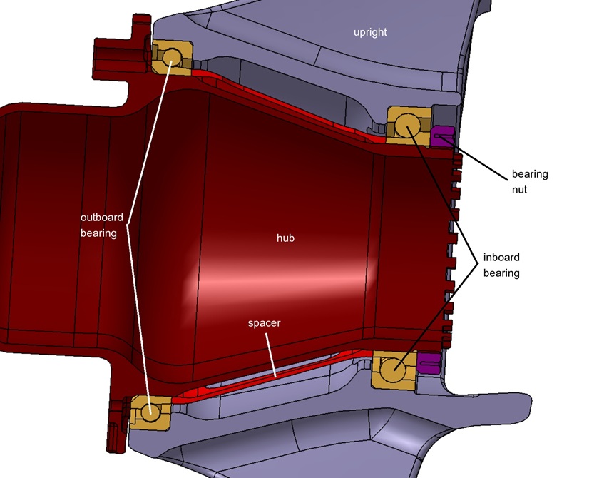
Determining the correct bearing preload cannot be performed by evaluating the bearing in isolation. The effective preload experienced by the rolling elements during operation depends heavily on the structural compliance of surrounding components:
To accurately predict the operational preload window, structural engineers must simulate the entire corner assembly—including hub, spindle, bearings, upright, and fastening hardware—as a fully coupled compliant system.
4. Efficient FEA Modeling Strategy for Wheel Bearings
Explicitly modeling dozens of individual rolling elements with full 3D non-linear contact surfaces in a full-vehicle or suspension upright simulation is computationally prohibitive due to mesh density requirements and severe contact convergence challenges.

To bypass this limitation while preserving full structural fidelity, a simplified mathematical modeling methodology can be implemented:
- Non-Linear Equivalent Stiffness Elements: The mechanical response of the ball-raceway Hertzian contact is represented using non-linear spring networks or specialized user-defined elements tuned to match theoretical load-deflection curves ($F = k \cdot \delta^{3/2}$).
- Preload Application: Axial preloads are introduced via thermal contraction of equivalent sleeves or direct bolt-pretension force vectors across the inner raceways.
- Assembly Flexure Capture: The model retains the full 3D geometry of the hub and upright, capturing housing ovalization and shaft bending under extreme cornering loads.
5. Summary Comparison
| Preload State | Raceway Contact Pressure | Rolling Resistance / Drag | Wheel Group Camber Stiffness | Primary Failure Mode |
|---|---|---|---|---|
| Excessive Preload | Extremely High | High (Power loss) | Very High | Subsurface fatigue, pitting, thermal seizure |
| Optimal Preload Window | Controlled / Uniform | Minimized | Nominal / Stable | Maximized fatigue life & cornering stability |
| Insufficient Preload | Non-uniform / Cyclic | Low | Compromised / Reduced | Raceway hammering, loss of camber control |
6. Conclusion
Optimizing wheel bearing preload in racing vehicles requires an integrated numerical approach. By coupling the compliance of surrounding upright and hub structures with non-linear bearing stiffness formulations in FEA, engineers can reliably identify the optimal preload window—maximizing component durability, preserving suspension geometry under load, and eliminating unnecessary drivetrain drag.
