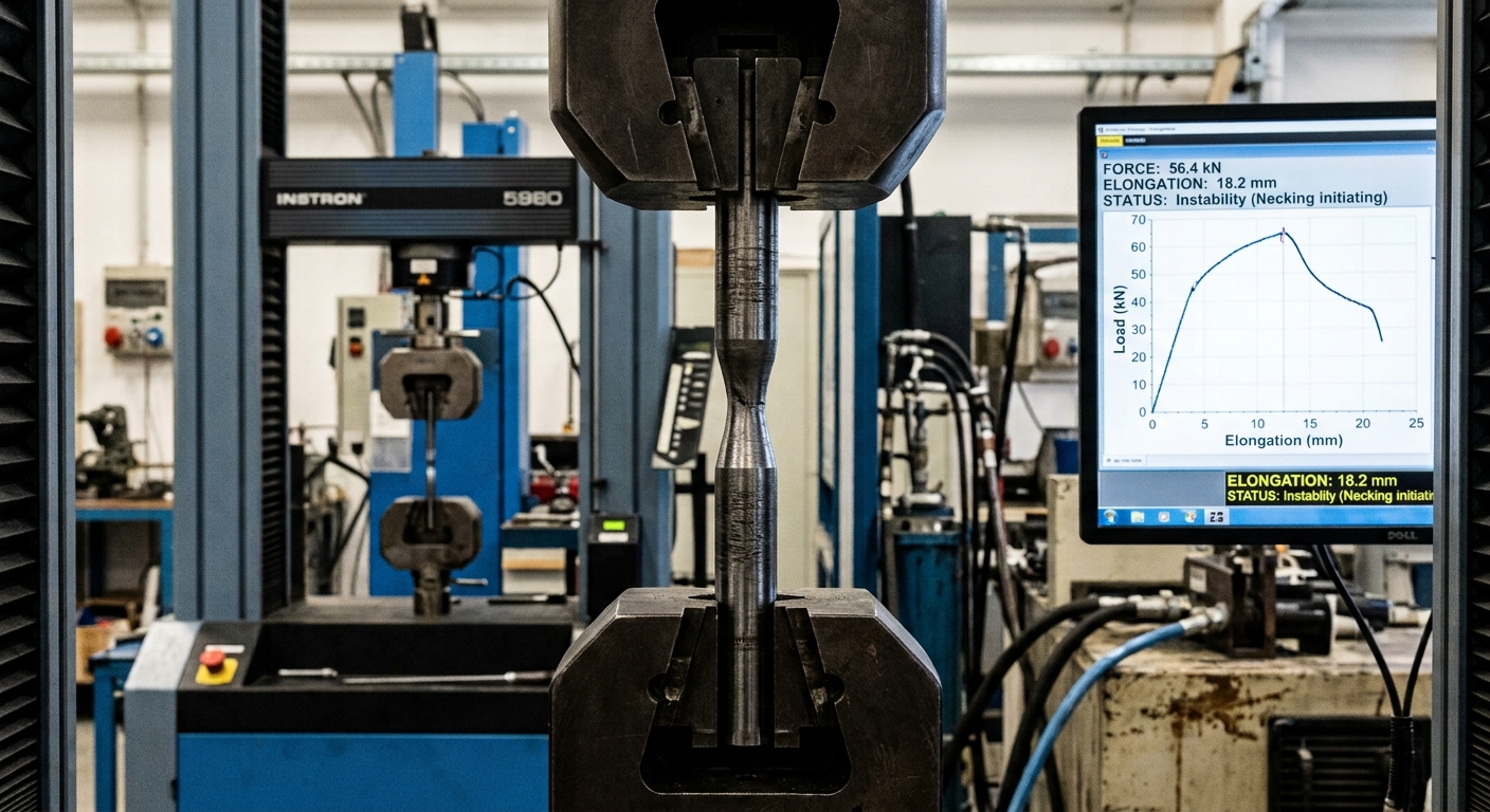
Beyond the Plastic Behaviour of Ductile Materials: Non-Linear FEA and Structural Reserves
Executive Summary
Accurately determining the load-bearing limits of a mechanical component is essential to guarantee structural safety while quantifying margin reserves under exceptional load conditions. For ductile materials, traditional linear elastic verifications rely heavily on comparing equivalent Von Mises stresses against the material’s yield strength (σyield). However, when high operational or accident loads push the stress state past the elastic limit, stopping at a purely elastic analysis can lead to overly conservative or structurally inaccurate conclusions. Entering the plastic regime allows engineers to evaluate stress redistribution and unlock the full structural reserve of ductile components.
1. From Von Mises Stress to the Plastic Reserve
In classical structural analysis, ductile metals (such as structural steels and aluminum alloys) are evaluated using yield criteria that identify the onset of permanent deformation. The Von Mises criterion provides a reliable metric for predicting elastic limits under multiaxial stress states.
When a localized region reaches σyield, it does not imply immediate catastrophic failure. Unlike brittle materials, ductile materials possess a significant capacity to absorb energy through localized plastic deformation. As yielding initiates:
- Stress Redistribution: The yielding zone loses stiffness, forcing surrounding material in the elastic range to absorb additional load increments.
- Load Capacity Beyond First Yield: Cross-sections can continue carrying higher bending moments or axial forces until a fully plasticized mechanism (such as a plastic hinge) develops.
- Safety Margins Evaluation: Understanding post-yield behavior allows engineers to accurately calculate ultimate capacity under extreme or accidental loading scenarios.

2. Linear Elastic Calculations and Neuber’s Correction
When performing a purely linear elastic Finite Element analysis, the solver assumes that stress and strain remain proportional indefinitely (σ = E · ε). If localized stress concentrations exceed the yield strength (σ > σyield), the linear model reports unrealistically high fictitious elastic stresses and fails to reflect physical stress redistribution.
Running a full non-linear material FEA can be computationally expensive or impractical during early design phases. In such cases, engineers can estimate actual elastoplastic stress and strain at notch roots using the Neuber Correction method. By asserting that the product of elastic stress and strain equals the product of true elastoplastic stress and strain, Neuber’s rule provides a fast, reliable analytical bridge between linear elastic FEA results and real plastic strain values.
3. Implementing Full Plasticity in Non-Linear FEA
When precise residual deformations or global plastic collapse loads must be evaluated, non-linear material laws must be defined directly inside the solver. Naive insertion of nominal stress-strain data into non-linear solvers often generates convergence failures or unphysical results.
Converting Engineering Data to True Stress and True Strain
Standard tensile testing yields Engineering Stress (σeng) and Engineering Strain (εeng), which assume a constant cross-sectional area. In finite element solvers undergoing finite strains, material models require True Stress (σtrue) and True Plastic Strain (εptrue):
εtrue = ln(1 + εeng)
εptrue = εtrue − (σtrue / E)
Bilinear vs. Multi-Linear Hardening Models: Depending on the required precision, engineers can adopt a simplified bilinear hardening model (elastic modulus E followed by a constant plastic tangent modulus ET) or a full multi-linear stress-strain curve. Selecting the appropriate model depends on whether the goal is a rapid plastic collapse check or precise permanent set prediction.
4. Simulating Component Failure with Ductile Damage Models
Beyond plastic deformation and strain hardening, non-linear FEA allows engineers to capture the ultimate phase of structural degradation: material fracture. By coupling elastoplastic constitutive models with progressive Ductile Damage criteria (such as Johnson-Cook damage initiation and evolution laws), the solver can account for material failure under high plastic strains.
Once local damage reaches a critical threshold (D = 1), the material stiffness degrades completely, and technique such as element deletion can be applied. This allows for the realistic dynamic tracking of crack initiation, crack propagation, and complete structural separation, as demonstrated in the simulation video below.
5. Practical Challenges in Non-Linear Material Solvers
Simulating post-yield behavior and progressive damage requires robust non-linear incremental-iterative solvers (such as Newton-Raphson or Explicit dynamic procedures). Key numerical considerations include:
- Isotropic vs. Kinematic Hardening: Choosing isotropic hardening for monotonic loading vs. kinematic hardening for cyclic or fatigue scenarios (taking into account the Bauschinger effect).
- Mesh Sensitivity and Regularization: High stress/strain gradients in localized necking and damage zones require mesh refinement or energy-based regularization to prevent mesh-dependent results.
- Convergence Control: Balancing load step sizes, automatic time stepping, and residual tolerances to maintain numerical stability during rapid material softening and element deletion.
6. Conclusion
Simulating the plastic behavior and progressive damage of ductile materials opens the door to optimized, high-performance engineering designs that take full advantage of structural reserves while accurately predicting ultimate failure modes. Whether using analytical approximations like Neuber’s Correction on linear models or deploying advanced elastoplastic damage models, moving beyond linear assumptions transforms FEA into a true predictive tool for extreme structural endurance.
In Chapter 13 of my book, Computational Structural Engineering, I provide an extensive breakdown of non-linear material formulations, step-by-step guidance on converting test data for FEA solvers, and practical tips & tricks to overcome numerical convergence issues in industrial applications.
