Carbon Fiber Chair

Background

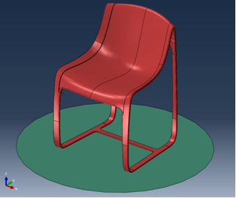
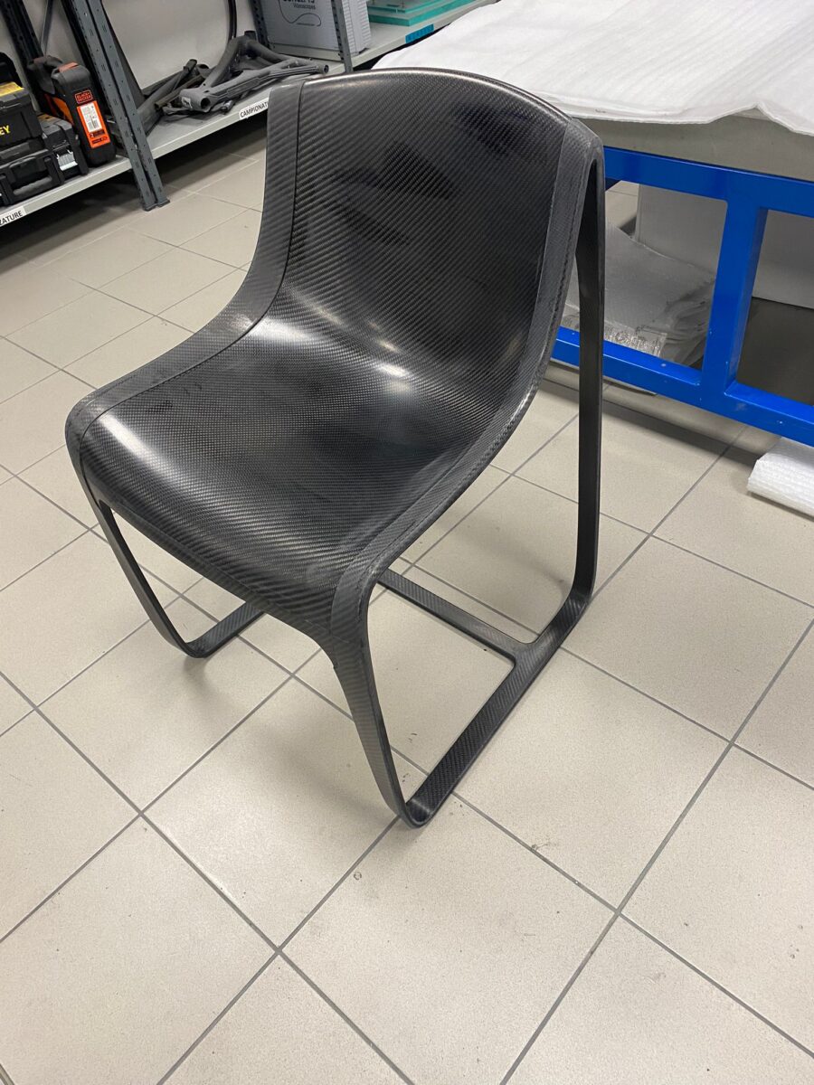
Even a simple and common object like a chair (Figure 1) requires a careful design evaluation to guarantee its integrity in the all-days usage. It has to be safe, but it also has to be light to allow for easy movements from one place to another and while taking a seat.

Figure 1 – Carbon Fiber chair model laying on the floor

The Challenge

The aim of the Customer was to build a chair in composite material that have to withstand the Normative Rules of integrity and safety. The Normative foresees that the chair has not to overturn when a person is seated on it, it has to be stiff enough and highly robust to support a person weight and, last but not least, has to be as light as possible.

CG CAE was chosen for our extensive experience with composite materials and their application in Finite Element Modeling, for our in-depth knowledge of advanced modeling techniques, and for the speed with which we are able to deliver high-quality results to our Clients.

The FE Model

Considering the request of the Customer the chair was modeled with shell elements (the best candidates to simulate Composite Materials, provided that parts are thin enough). The material was chosen among the possible alternatives proposed by the Customer and the final Lay-Up was optimized with some analysis iterations to guarantee strength, stiffness, lightness and stability.

The studied load conditions were the application of the person weight and the simulation of the overturning to check which force value would cause it.

Stability analyses (both linear buckling and post-buckling) were also performed for the sake of the safest possible configuration.

Some results

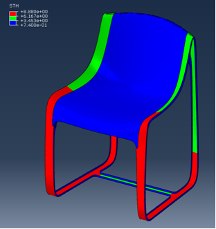
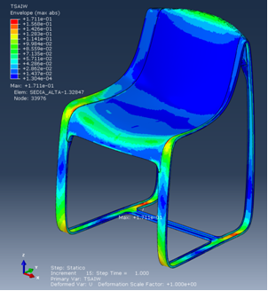
Figure 2 shows the optimized thickness of the final Lay-Up, while Figure 3 shows the Tsai-Wu Failure Index for one of the load cases under investigation

Figure 2 - LayUp thickness
Figure 3 - Tsai-Wu Failure Index

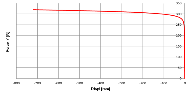
The graph in Figure 4 shows the force vs. displacement evaluated during the simulation of the overturn of the seat and the animation in Figure 5 shows the behavior while simulating the overturn.

Figure 4 - Force vs displacement for the tip over case

Figure 5

Conclusions

Based on the simulation results some prototypes were produced and tested with a very good correlation between test and numerical model.

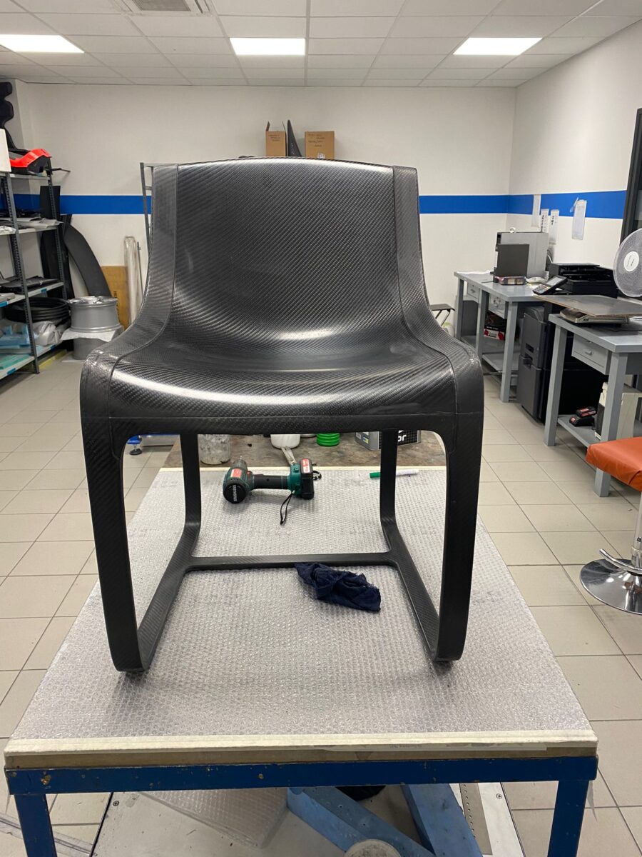
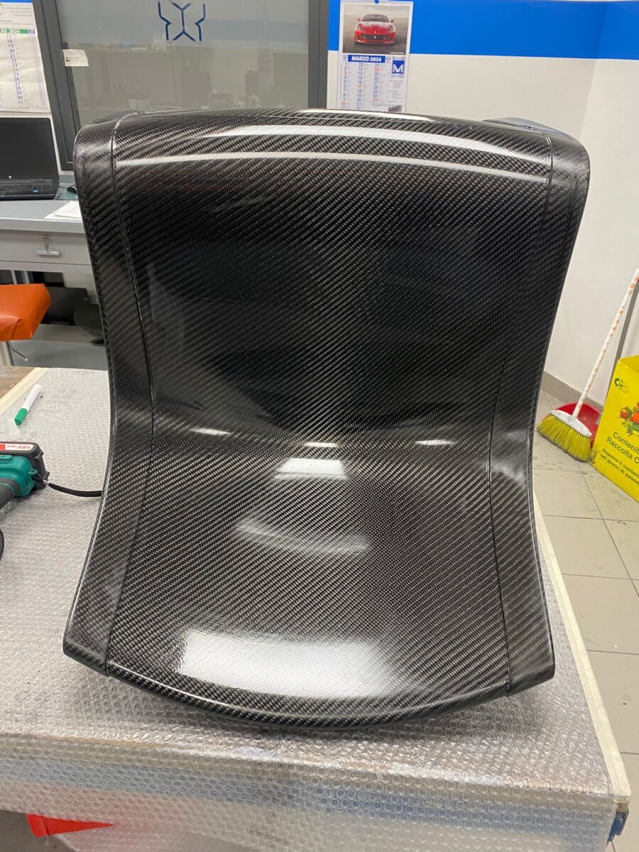
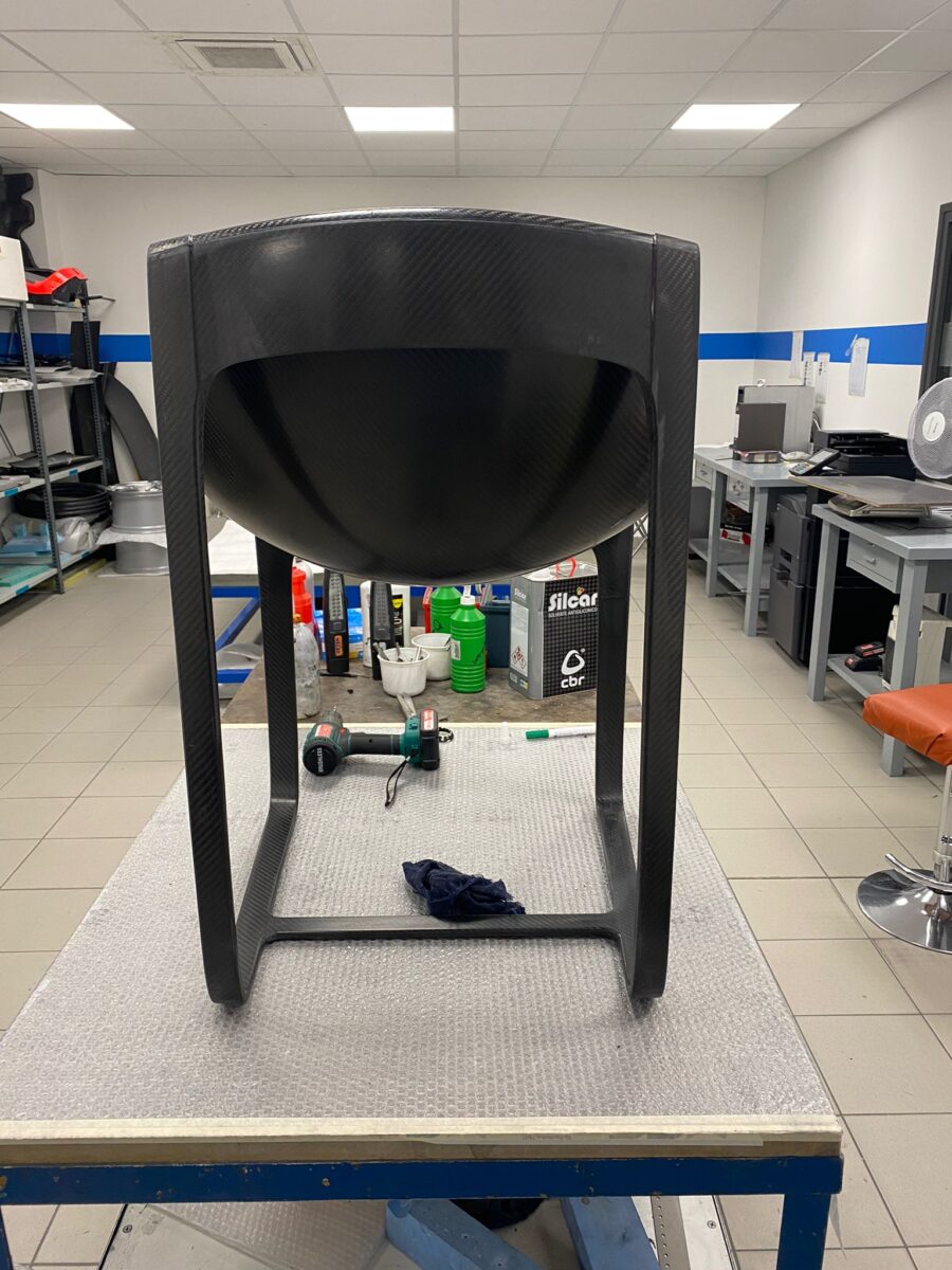
Figure 6 shows the first sample realized following CG CAE’s indications.

Figure 6