The First Ply Failure Approach in Composite Structures: Is It Really the End?
Executive Summary
Imagine this scenario: you have spent days setting up a complex finite element model for a composite structure. You’ve meticulously defined the layup, the orientations, and the boundary conditions. You run the analysis, check the results, and suddenly you see it: one single ply has reached a Failure Index equal to 1.0. According to the standard First Ply Failure (FPF) approach, your entire component has just failed. While FPF provides absolute safety during nominal operations, it tells only a fraction of the story and often leads to over-engineered, heavy laminates. Moving beyond this limit allows engineers to evaluate stress redistribution and unlock the full structural reserve of composite components.
1. The Hidden Load Reserves in Laminates
Unlike ductile metals, where yielding allows stresses to redistribute smoothly, composite fibers (especially carbon) are essentially brittle. However, a composite laminate is a team effort. Does a single localized failure really mean the whole structure will collapse? Not necessarily. Consider a typical multi-angle layup (like [0° / ±45° / 90°]):
- Matrix Cracking Before Fiber Failure: Off-axis 90° plies might experience matrix cracking long before the primary load-bearing 0° fibers even break a sweat.
- Load Redistribution: The damaged plies lose stiffness, forcing the surrounding intact plies to absorb additional load increments.
- Mass Optimization: If we stop the analysis at the exact moment that first 90° ply fails, we throw away a massive amount of structural reserve. Designing strictly around FPF across all ultimate load cases completely defeats the lightweight purpose of using composite materials.
2. Going Beyond: Progressive Failure Analysis
What happens if we keep pushing the load? To find out, we have to move past static, linear assumptions and embrace Progressive Failure Analysis (PFA).
By implementing specific damage initiation criteria and energy-based damage evolution laws within a non-linear solver like Abaqus, we can simulate what happens after that first ply cracks. The solver handles the complex mechanics of damage accumulation in both fibers and matrix.
Ply Discounting Mechanism: As progressive damage occurs, the FE software dynamically reduces the elastic stiffness properties of the damaged integration points. This controlled softening allows the load to realistically reroute into the surrounding, intact composite layers without triggering immediate numerical or structural collapse.
3. A Practical Example: Plate Under Uniform Pressure
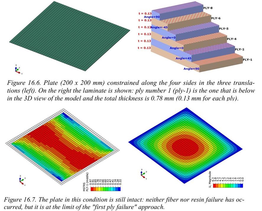
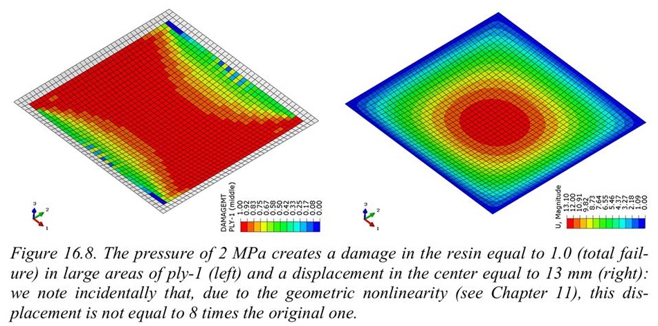
To see just how conservative the FPF approach can be, we can look at the case study detailed in § 16.3 of the book “Computational Structural Engineering”.
When analyzing a composite plate under uniform pressure, the linear First Ply Failure criterion flags a failure at a relatively low pressure level. However, by turning on progressive damage modeling, the non-linear simulation reveals a completely different reality. The plate successfully redistributes internal stresses and survives up to a pressure of 2.0 MPa before suffering a catastrophic, global failure.
4. Conclusion
The takeaway? FPF is a great baseline for everyday operating conditions, but if you want to optimize mass and understand the true ultimate limits of your structure, Progressive Failure Analysis is the way to go. Moving beyond linear assumptions transforms composite FEA into a true predictive tool.
For an in-depth exploration of these phenomena, you can refer to Chapter 16 of my book, Computational Structural Engineering, where I provide detailed breakdowns of damage criteria, non-linear material formulations for composites, and practical guidance on capturing the true strength of laminates.
